


Air Compressor Sizing Guide: How to Calculate CFM, PSI & System Components (2026)

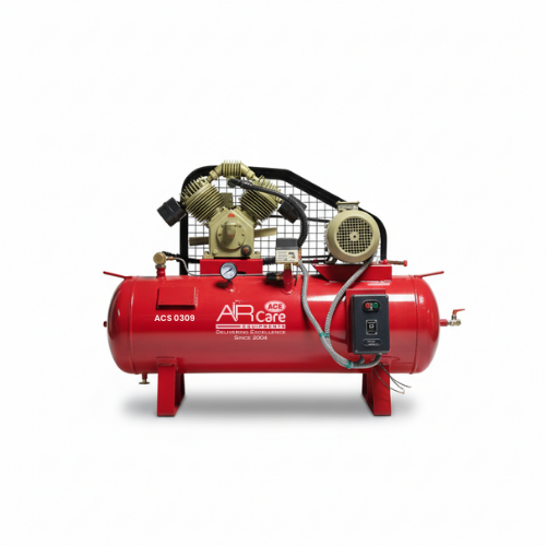
Selecting the right industrial compressed air system is one of the most critical decisions for any manufacturing plant, workshop, or healthcare facility. An undersized system results in low pressure, tool failure, continuous motor strain, and unexpected downtime. Conversely, an oversized system leads to excessive energy bills, high upfront costs, and inefficient short-cycling.
This comprehensive air compressor sizing guide breaks down how to calculate your airflow needs (CFM), determine required operating pressure (PSI), and choose the correct auxiliary equipment for peak plant efficiency.
1. Core Sizing Metrics: CFM, PSI, and Duty Cycles
To size an air compressor accurately, you must understand three foundational metrics:
CFM (Cubic Feet per Minute): Measures the volume of air generated per minute. Tools that run continuously (like spray guns, sanders, or CNC machines) demand high CFM ratings.
PSI (Pounds per Square Inch): Measures the force or pressure of the compressed air. Standard pneumatic tools generally operate at 90 PSI, whereas high-pressure manufacturing applications like laser cutting may require 125 to 175+ PSI.
Duty Cycle: Indicates how long a compressor can run continuously during a given time frame. Reciprocating piston models usually have a 50%–70% duty cycle, while continuous-duty systems from top rotary screw air compressor manufacturers are built for 100% uninterrupted operation.
2. How to Calculate Total System CFM and Pressure
Calculating your facility's total airflow demand involves three simple steps:
Step 1: Tally Total Tool CFM
List every pneumatic tool or machine that will operate simultaneously. Sum up their CFM requirements at operating pressure (typically 90 PSI).
Step 2: Apply a Safety Buffer (25%)
Multiply your total CFM by 1.25 to account for system pressure losses, minor pipe friction, and future tool additions.
$$\text{Required Airflow (CFM)} = \left(\sum \text{Simultaneous Tool CFM}\right) \times 1.25$$
Step 3: Match the Highest PSI
Identify the single tool that requires the highest operating pressure. Your compressor must supply at least 15 to 20 PSI above this requirement to compensate for pressure drop across piping and treatment equipment.
For a step-by-step mathematical example and tool airflow chart, refer to our detailed Air Compressor Sizing Guide (CFM & PSI).
3. Essential Auxiliaries: Receiver Tanks and Air Treatment
Sizing the air compressor pump is only half the battle; downstream auxiliary components must be sized to match your airflow output.
+------------------+     +-------------------+     +------------------+     +------------------+
|  Air Compressor  | --> | Air Receiver Tank | --> | FRL Unit Assembly | --> | Pneumatic Tools  |
|  (Piston / Screw)|     | (Pressure Vessel) |     | (Filter/Reg/Lub) |     | / CNC Machinery  |
+------------------+     +-------------------+     +------------------+     +------------------+
A. Air Receiver Tank Sizing
An air receiver tank stores compressed air under pressure, smoothing out sudden demand spikes and preventing rapid motor cycling. As a general rule of thumb:
$$\text{Tank Volume (Gallons)} = \text{Compressor Output (CFM)} \times 3 \text{ to } 5$$
For instance, a 50 CFM compressor requires a 150 to 250-gallon pressure vessel. To learn more about vessel calculations, explore our Air Receiver Tank Sizing resource.
B. Point-of-Use FRL Assemblies
Before compressed air enters your pneumatic equipment, it should pass through an FRL filter regulator lubricator assembly. The filter cleans particulates and moisture, the regulator holds working pressure steady, and the lubricator protects moving internal components.
4. Specialized Sizing: Medical Air Compressor Oil Free Systems
In critical healthcare environments—such as hospital operating theaters, ICUs, and dental suites—air purity is non-negotiable.
Unlike standard industrial units, a medical air compressor oil free system must be sized for peak clinical ventilation demand while strictly adhering to ISO 8573-1 Class 0 air purity standards. They utilize multi-stage desiccant drying and specialized filtration to prevent toxic hydrocarbon vapor or moisture from entering patient breathing circuits.
Frequently Asked Questions (FAQs)
Q1: What happens if I undersize my air compressor?
An undersized air compressor cannot maintain target system pressure (PSI) during peak operations. This causes pneumatic tools to lose torque, leads to continuous running and overheating, accelerates mechanical wear, and significantly increases electricity costs due to continuous unloading cycles.
Q2: How do I size an air receiver tank for my compressor?
A standard rule of thumb is to allow 3 to 5 gallons of tank capacity for every 1 CFM of compressor output. For example, a compressor delivering 20 CFM should be paired with a 60 to 100-gallon air receiver tank to absorb pressure surges and reduce motor start-stop cycles.
Q3: Why is an FRL unit necessary after sizing my compressor?
While sizing guarantees your compressor delivers sufficient volume (CFM) and pressure (PSI), an FRL (Filter, Regulator, Lubricator) unit protects your tools at the point of use. It strips out fine moisture and rust, regulates steady downstream pressure, and provides oil mist lubrication for continuous mechanical protection.



Comments